Topic: Tech Talk

DIYers: Save time and money by learning the secrets of appliance repair

Posted on January 14, 2015 by - Academy Talk, Career Talk, Tech Talk

Ivey Refrigerator Repair copy
 
Let’s face it: appliance repairs are expensive due to the real costs of running a full-time, professional appliance repair business. That’s why so many folks are trying to save time and money by learning how to fix their own appliances. And how ’bout the supreme satisfaction that comes from kicking major appliance boot-ay? BOOYAH!

Appliantology.org is a powerful repair resource for DIYers. You’ve got professional appliance techs giving you personal help. But all too often, that help comes to a screeching halt when you gotta have basic electrical troubleshooting skills to finish the job, such as reading schematic diagrams and understanding the technology that you’re working on.

DIYers are a diverse group but, in my decades working with them online, I see that most DIYers share two characteristics: they have above average to great mechanical skills, but are weak on electrical skills.

With today’s increasingly computerized appliances, unless you have a minimum baseline of electrical troubleshooting skills, you’re just going to be flailing about blindly in a sea of technical symbols and words for all but the simplest repairs. Any electrical explanations or instructions offered to you will just sound like Chinese. You can see the problem here.

What’s a bruthah from anothah muthah to do?

Samurai to the rescue! The electrical and troubleshooting skills you need are very learnable and affordable at the Samurai Tech Academy.

The Fundamentals of Appliance Repair course would be an awesome boost to your ability to repair all kinds of things around the house. Basic electricity, electronics, gas, electric motor systems, and troubleshooting with schematics are all timeless skills with broad application that will give you valuable insight into the inner workings of numerous electro-mechanical systems in your home.

You can acquire these skills inexpensively and conveniently in our up-to-date, comprehensive, online Fundamentals of Appliance Repair training course. The course tuition will pay for itself after just one or two DIY repairs!

It’s an investment in the most valuable asset you have: YOU!

Other methods of technical training available today are DVD packages, in-person training, and correspondence courses. See how online learning compares with these other training methods.

Dance with me now:

  • Modern appliances are complicated electro-mechanical machines that are increasingly using single-board computers to control them.
  • Tech help at Appliantology.org can only take you so far if you don’t understand the underlying technology you’re dealing with and you can’t use schematics to troubleshoot and make basic electrical measurements.
  • The Fundamentals of Appliance Repair course teaches you all of the basics you need to ascend to a higher level of DIY ability.
  • The skills you learn in the course are timeless and have broad application.
  • You could even earn extra beer money on the side while you keep your regular job.
  • Better yet, do appliance repair full-time and earn up to $120K/year as a skilled appliance tech!
  • Complete the Free Sample Course to get a foretaste of the empowering wisdom that awaits you along with a discount coupon!

Dryer Schematic Quiz, Part 2

Posted on January 10, 2015 by - Tech Talk

Dryer Schematic Quiz 2 - Click for Larger View (opens in a new window)

Dryer Schematic Quiz 2 – Click for Larger View (opens in a new window)


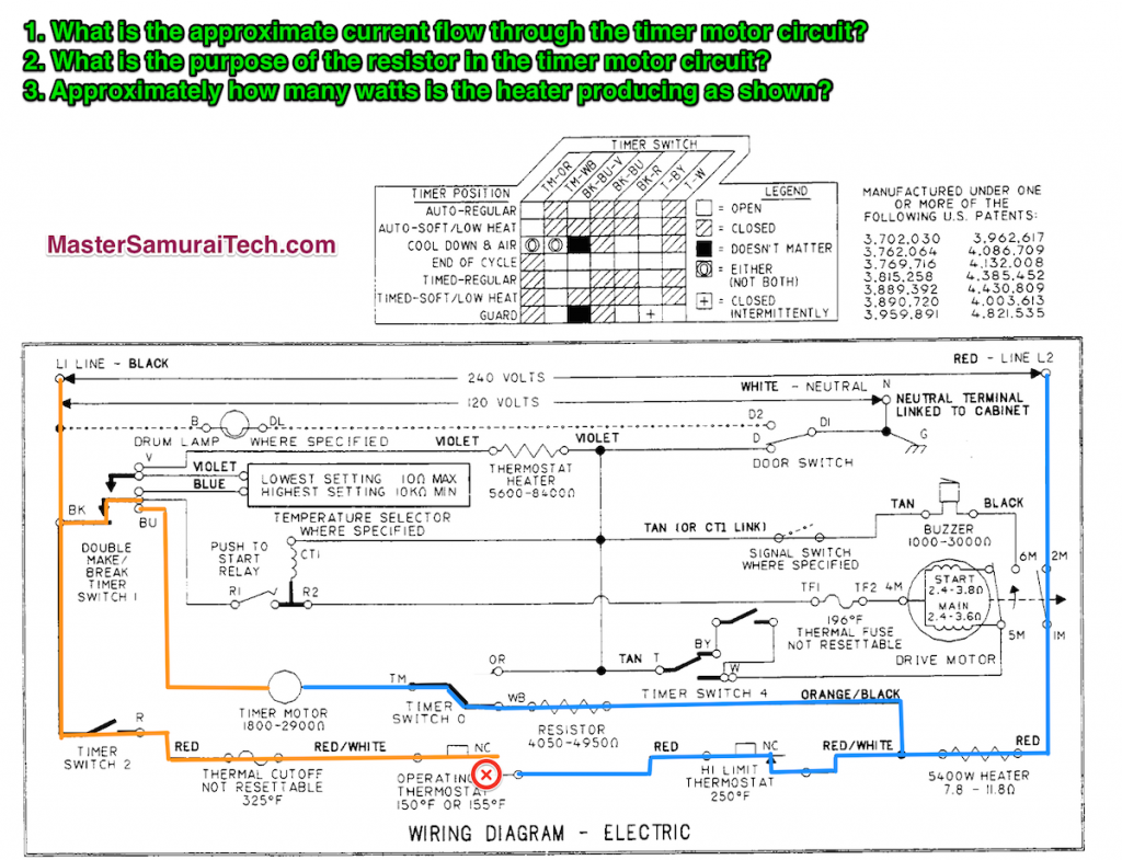
1. To calculate the current flow in this simple series circuit, you first need to calculate the total circuit resistance.

The heater resistance is given as a range so, for simplicity, let’s assume something in the middle, say 8 ohms.

The resistor ohms are also given as a range so let’s again use something in the middle, say 4500 ohms.

Similarly, a mid-range resistance on the timer motor would be 2200 ohms.

Adding these up, the total circuit resistance is about 6708 ohms. Now we can calculate total circuit current using Ohm’s Law:

I = E ÷ R = (total power supply voltage) ÷ (total circuit resistance) = 240 vac ÷ 6708 ohms = 0.036 amps.

2. The timer motor is a 120 vac synchro motor but the circuit is supplied with 240 vac. The purpose of the resistor is to drop some voltage so that the voltage across the timer motor is something less than 120 vac. How much less? You can calculate the voltage drop across the resistor because we know the circuit current, 0.036 amps. In a series circuit, current is the same at all points and through every load. Therefore, the voltage drop across the resistor is

E = I x R = (0.036 amps) x (4500 ohms) = 162 vac.

The remaining voltage is dropped across the heater and timer motor according to their resistances.

3. Ohm’s Law again:
P = I2 x R = (circuit current)2 x (heater resistance)
= (0.036)2 x (8 ohms) = 0.01 watts

Still confused? I explain and demystify circuits, reading schematics, troubleshooting with schematics, motors, and all the other basic skills that every appliance tech should have in our Fundamentals of Appliance Repair training course.

Dryer Schematic Quiz

Posted on January 8, 2015 by - Tech Talk

Dryer Schematic Quiz

Dryer Schematic Quiz – Click for Larger View (opens in a new window)


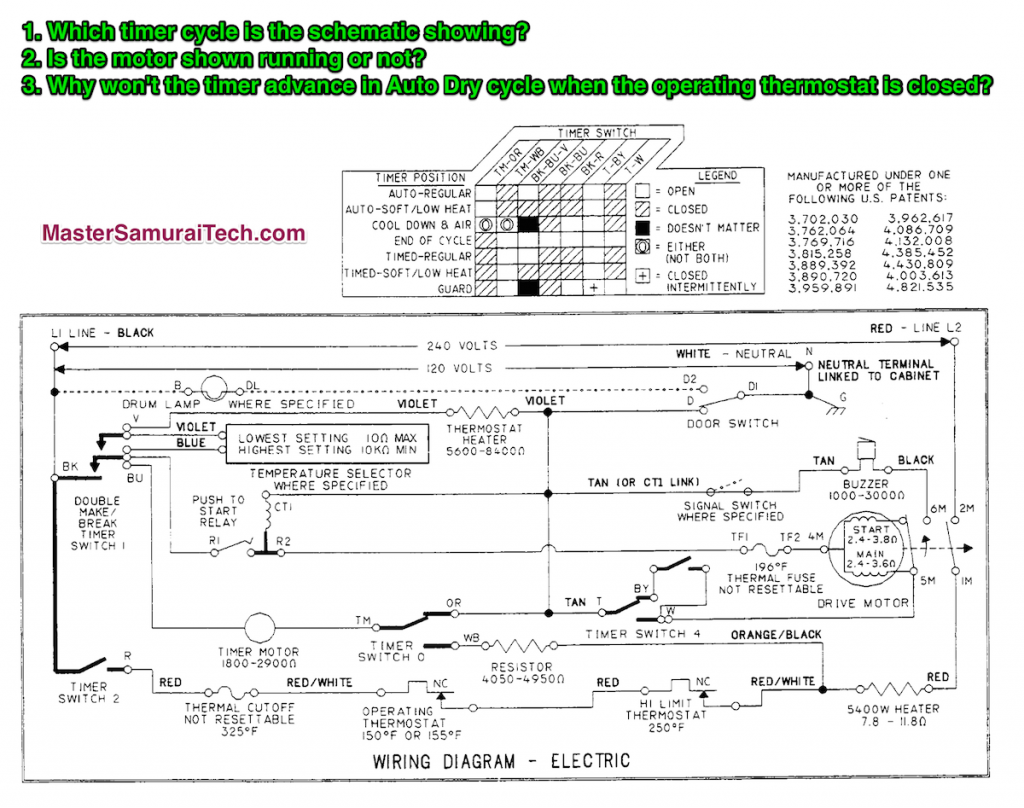
1. Which timer cycle is the schematic showing?

Looking at the timing chart, we see that the cycles on this dryer fall into two main groups: auto and timed. The big distinction between the two is timer contacts TM-OR (timed dry cycles) and TM-WB (auto dry cycles). Since the schematic shows that the TM-OR contacts are made, then we know we’re in a timed dry cycle. Checking the state of the other contacts listed in the timing, we see that the schematic shows them all as open. Therefore, we know that this dryer schematic is showing the dryer at the End-of-Cycle. Which also helps answer the next question…

2. Is the motor shown running or not?

We know from the forgoing analysis that the dryer is shown at end-of-cycle, so the motor is not running. But you can also tell by looking at the centrifugal switch contacts on the motor. They are shown in the retracted state meaning the motor is stopped.

3. Why won’t the timer advance in Auto Dry cycle when the operating thermostat is closed?

In Auto Dry, the timer chart shows timer contacts TM-WB are made. With this in mind, trace L1 to the timer motor. L1 comes through timer contacts BK-BU to one side of the timer. L1 also comes through timer contacts BK-R, through the thermal cutoff, operating thermostat, and high limit to one side of the heater. But it also branches off through the resistor and timer contacts TM-WB to the other side of the timer. Since both sides of the timer have L1, the voltage difference across the timer is zero and the timer motor does not run.

Still confused? I explain and demystify circuits, reading schematics, troubleshooting with schematics, motors, and all the other basic skills that every appliance tech should have in our Fundamentals of Appliance Repair training course. Complete our free Sample course and get a discount off your tuition.

Simple Circuit Survey

Posted on January 6, 2015 by - Tech Talk

Simple Circuit Survey

Simple Circuit Survey


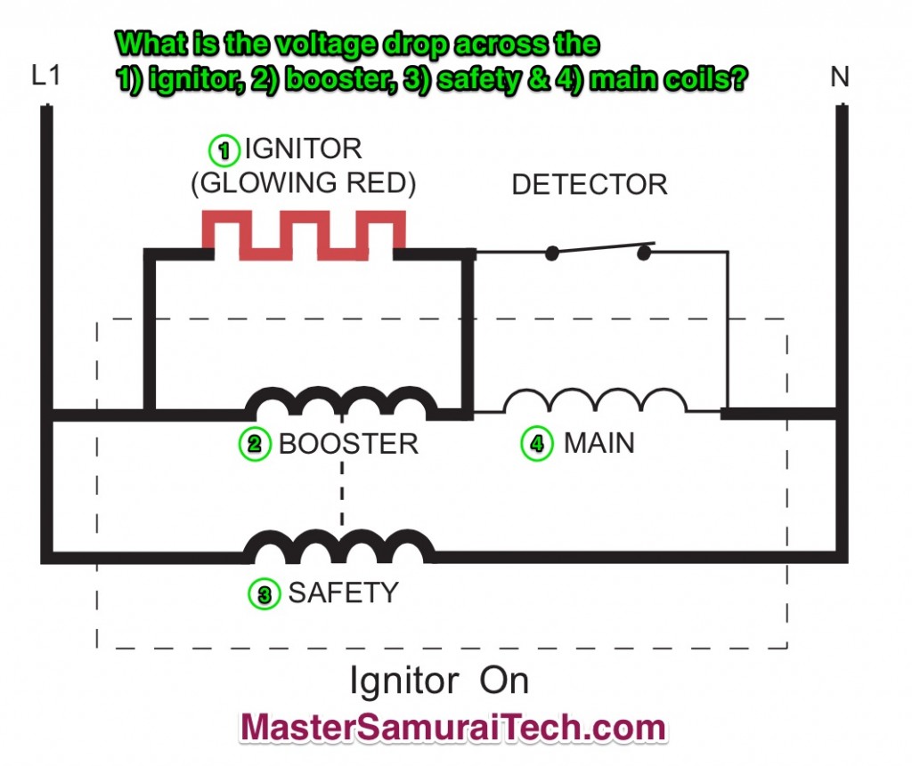
Start by noting the power supply. It’s called out as L1 to N. So we know that the power supply to this circuit is 120 VAC.

Ignore the thickness of the lines in the drawing; it doesn’t mean anything.

Since the ignitor is glowing, we know that 1) we have a valid power supply, and 2) current is flowing, so there will be a voltage drop across the ignitor (the load) and work is being done (producing heat).

Next, we note that the ignitor, booster, and safety are all in parallel with each other. From the Fundamentals of Appliance Repair training course, we know that the voltage in each parallel circuit is equal to the supply, in other words, 120 VAC in each leg. That’s just the way circuits work.

“But what about the voltage drop across the main coil— doesn’t that subtract from the voltage available to drop across the ignitor and booster?”

Ah, Grasshoppah, let’s look at that voltage drop across the main coil. Notice that the detector is closed. As such, it is shunting the current around the main coil because current will take the path of least resistance. Since there is no current flow through the main coil, the voltage drop across the main coil is effectively zero.

So the answers are:

1. Ignitor: 120 VAC
2. Booster: 120 VAC
3. Safety: 120 VAC
4. Main: 0 VAC

Still confused? Take the Fundamentals of Appliance Repair training course and hone those troubleshooting skills. Complete the free Sample Course and get a discount coupon!

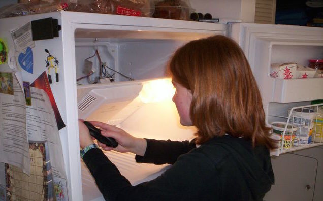
Do You Know the Secrets for Troubleshooting Warm Refrigerators?

Posted on January 4, 2015 by - Tech Talk

Refrigerator Flow Chart Quiz

Refrigerator Flow Chart Quiz

Also, the refrigerator is plugged in, the doors close properly, and the condenser coil is clean.

What’s the next thing to check?

Bad control board, right? Nope. What’s your next guess?

Check the defrost system, right? Nyet, tovarish!

This is an easy one IF you understand how refrigerators work. We reveal all the troubleshooting secrets for refrigerators in the Samurai Tech Academy’s Refrigerator Troubleshooting and Repair Training Course. From the simple to the fancy, from single evaporator units to fridges with two or more evaporators, from split-phase, single-speed compressors to inverter-driven, variable speed compressors, our Refrigerator course is the most comprehensive, up-to-date, and affordable training course out there.

If you’re looking to get into the appliance repair trade or to brush up your skills if you’re already in the trade, your search for an appliance repair school is over. Enter the Dragon.

Oh, BTW, the answer to the quiz is to see if the compressor is running. 🙂

Bonus question: How do you check the compressor operation? To be continued…